Service Technician Training: Electricity for Servicepeople, Part 22:
Electric Circuits, Continued: Contactor Latching Circuits
By Gary Weidner / Published March 2014

Any commercial or industrial machine that has the familiar “start” and “stop” pushbuttons almost certainly employs a latching circuit in its operation. Because latching circuits are so common and used in lots of pressure washers, understanding them is a must for the service technician.
The Latching Principle
Recall that a contactor is a device similar to a solenoid valve. When its coil is energized, the magnetism from the coil causes a plunger to move. In the case of the contactor, the movement of the plunger operates the heavy duty switches in the contactor.
A latching circuit does the following:
- It allows the contactor to be energized by a “start” pushbutton (or by any of several pushbuttons in different locations).
- It allows the contactor to be de-energized by a “stop” pushbutton (or by any of several pushbuttons in different locations).
- The functions of the “start” and “stop” pushbuttons can also be accomplished by automatic switches that are part of a pressure washer’s controls. For example:
~ The contactor can be energized when the trigger gun is squeezed on by means of a flow or pressure switch (“auto-start”).
~ The contactor can be de-energized by any device that can open the latching circuit. Examples of such devices are overload relays, shutdown timers, motor thermal overload sensors, inlet water pressure sensors, and high pressure switches (“auto-shutdown”).
How It’s Done
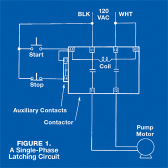
 Figure 1 presents a basic latching circuit. The layout shown is for 120 volts, single-phase. A 240 volt, single-phase circuit is identical in appearance. However, there are two differences: The contactor’s magnetic coil must be rated for operation at the same voltage as the power supply, 120 volts, or else 240 volts. In addition, the contactor’s main contacts must be rated to carry the pump motor current. (Remember, a motor draws twice as much current at 120 volts as it does at 240 volts.)
A few words about terminology. The contactor terminals for connection of the incoming power are almost always marked L1, L2, and so on. Note: a contactor may be designed to switch more than two lines, as in three-phase use. The contactor terminals for connection of the motor leads are almost always marked T1, T2, and so on.
Many contactor manufacturers use the designations A1 and A2 for the terminals that connect power to the magnetic coil. Likewise, many manufacturers use the designations 13 and 14 for the terminals of normally open auxiliary contacts. Auxiliary contacts are operated by the magnetic coil just like the main contacts. The difference is that they’re smaller and lighter duty, not intended to carry the main power flow.
The sequence of operation goes like this: (Assume that the pump motor is not running.) One side of the contactor coil (A2) is connected directly to one of the incoming power lines. The other side of the coil (A1) has two possible pathways to complete a connection to the other incoming power line.
One pathway is via the normally open momentary (spring loaded) “start” switch. When the operator presses the “start” switch, the coil is connected to both sides of the line, and the contactor is energized.
Here’s the clever part: When the “start” button is pressed and the contactor energized, a second pathway is created from A1 to the power line. Note that when the contactor is energized by pressing the “start” button, the normally open contact between terminals 13 and 14 closes. Closing this contact creates a pathway from A1 through 13–14 and the normally closed “stop” switch to the power line. So, when the operator removes his thumb from the “start” button, the contactor remains energized.
When the operator presses the normally closed momentary (spring loaded) “stop” switch, the connection from A1 to the power line is broken. The coil is de-energized, and the 13–14 contact opens. When the operator removes his thumb from the “stop” button, the contactor remains de-energized because the 13–14 contact is open, breaking one pathway, and the “start” switch is open, breaking the other pathway.
Three-Phase Latching Circuit
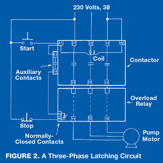
 Figure 2 presents the three-phase version of the previous circuit. The only differences are that the contactor switches three power lines instead of two, and the addition of an overload relay.
Single-phase pressure washer motors are usually built with internal overload protectors (the familiar reset button). Three-phase motors aren’t usually built with internal protection. They typically require separate, external protective devices. That’s the job of the overload relay. The layout in Figure 2, where the overload relay attaches to the outgoing terminals of the contactor, is fairly common.
The overload relay functions like a three pole circuit breaker, except that it doesn’t open the power lines itself. (Why build a set of heavy duty power contacts into the overload relay, when there’s already a set in the attached contactor?) As power flows from the T1, T2, T3 terminals of the contactor through the overload relay and out of its T1, T2, T3 terminals, the relay monitors the current flowing through it on each line.
If the current in any of the lines becomes excessive, the relay opens an internal normally closed contact that connects terminals 95 and 96. As you can see in Figure 2, opening the normally closed contact between 95 and 96 has exactly the same effect as pushing the normally closed “stop” switch: the contactor is de-energized.
In some European machines, the function of the overload relay is instead performed by an overload sensor that is built into the pump motor. The sensor has a normally closed contact that functions just like the 95–96 connection on the overload relay.
A Few Notes
Unlike the single-phase internal motor overload protectors, three-phase overload relays are commonly manufactured with trip current adjustments. Also, as with the A1, A2 and 13-14 terminals on the contactor, the 95–96 designation is not universal. Finally, the incoming power lines in Figure 2 are marked “230 volts, 3w.” The symbol w (Greek letter phi) is widely used to represent the word “phase.”
In the next chapter: more on contactor circuits.
Key Concepts
- Be sure to understand the latching principle; it’s widely used.
- A contactor latching circuit can be energized or opened by a variety of external switches, such as shutdown timers or pressure or temperature switches.
- Single-phase motors usually have internal overload protection. Three-phase motors usually do not, so a contactor overload relay is required to provide three-phase motor protection.


